Minghu Sculpture
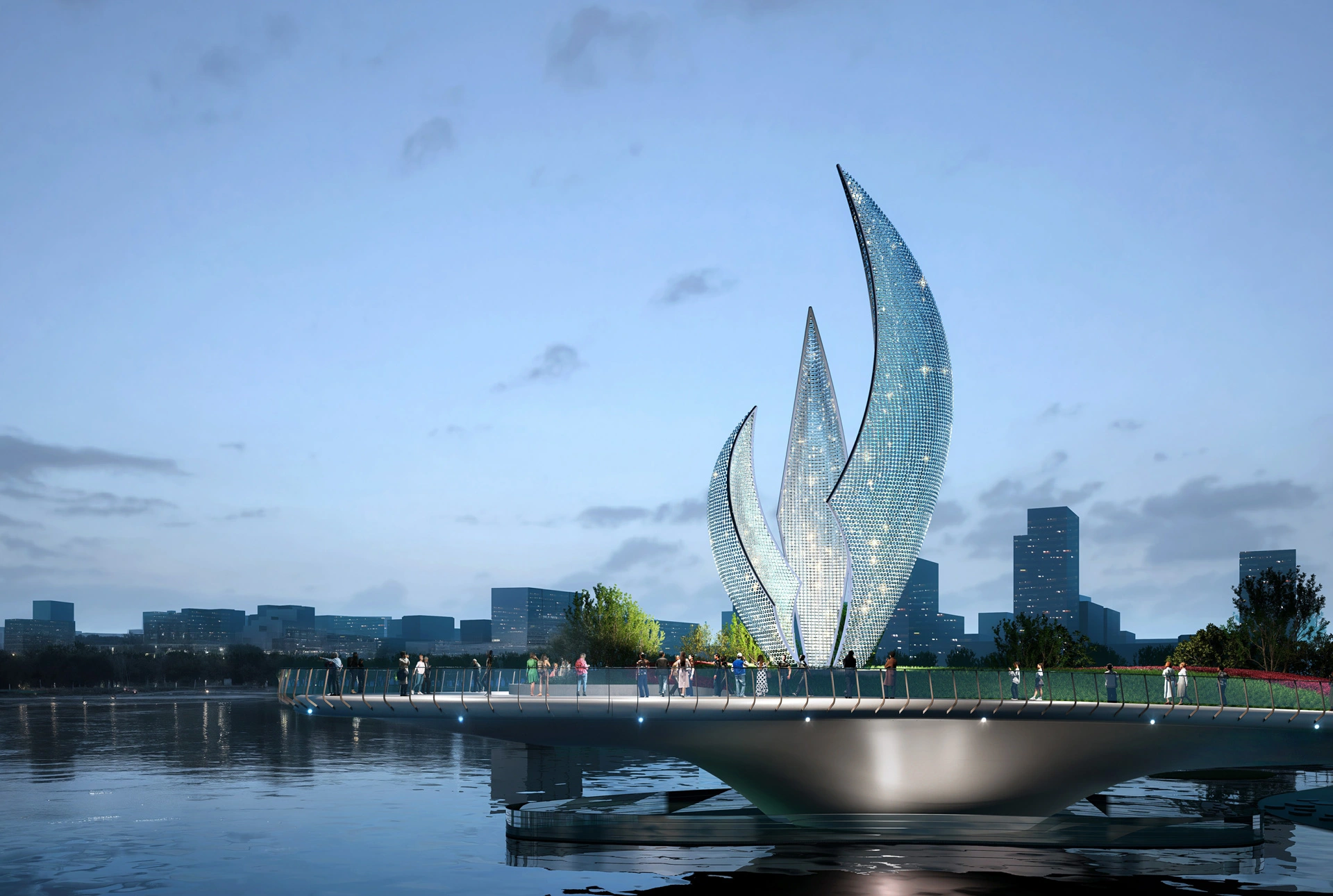
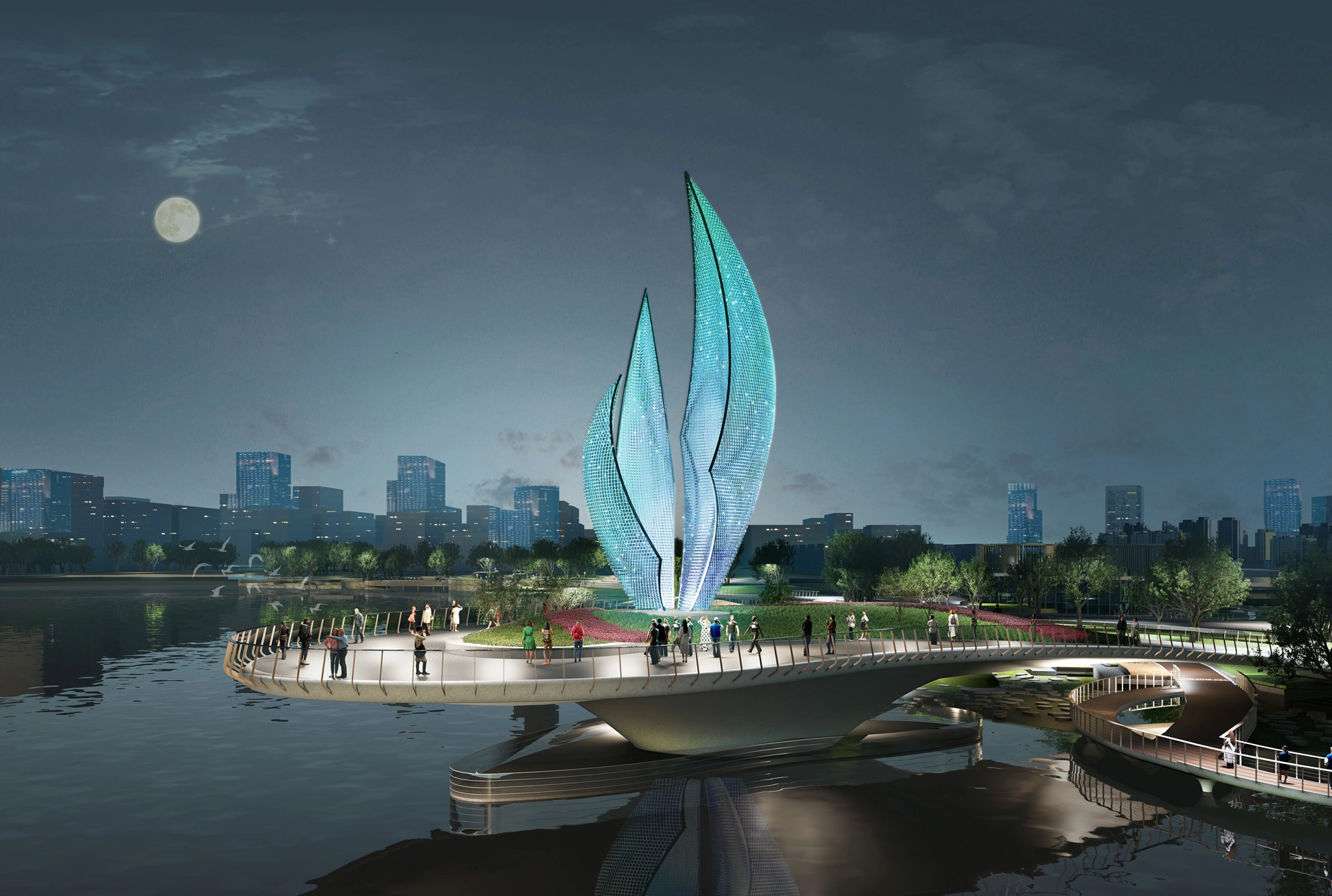
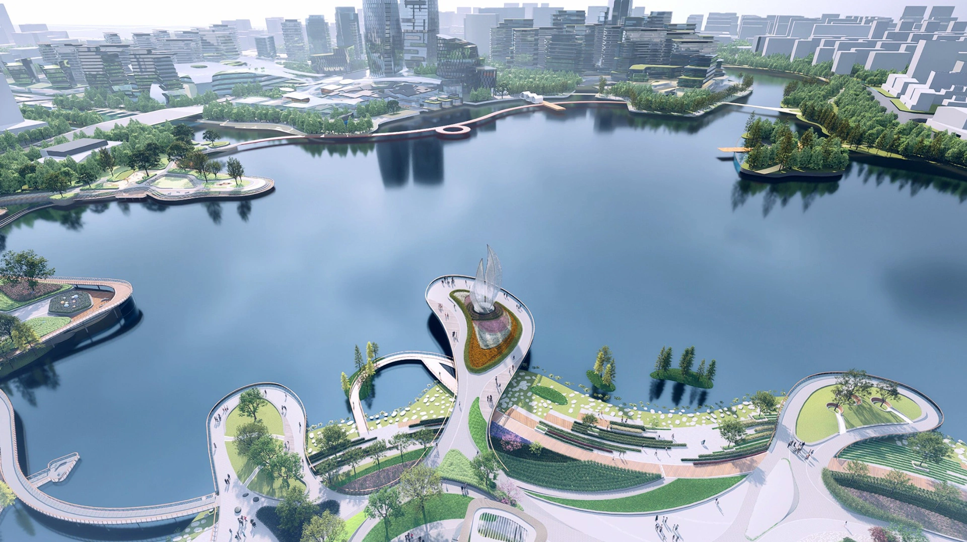
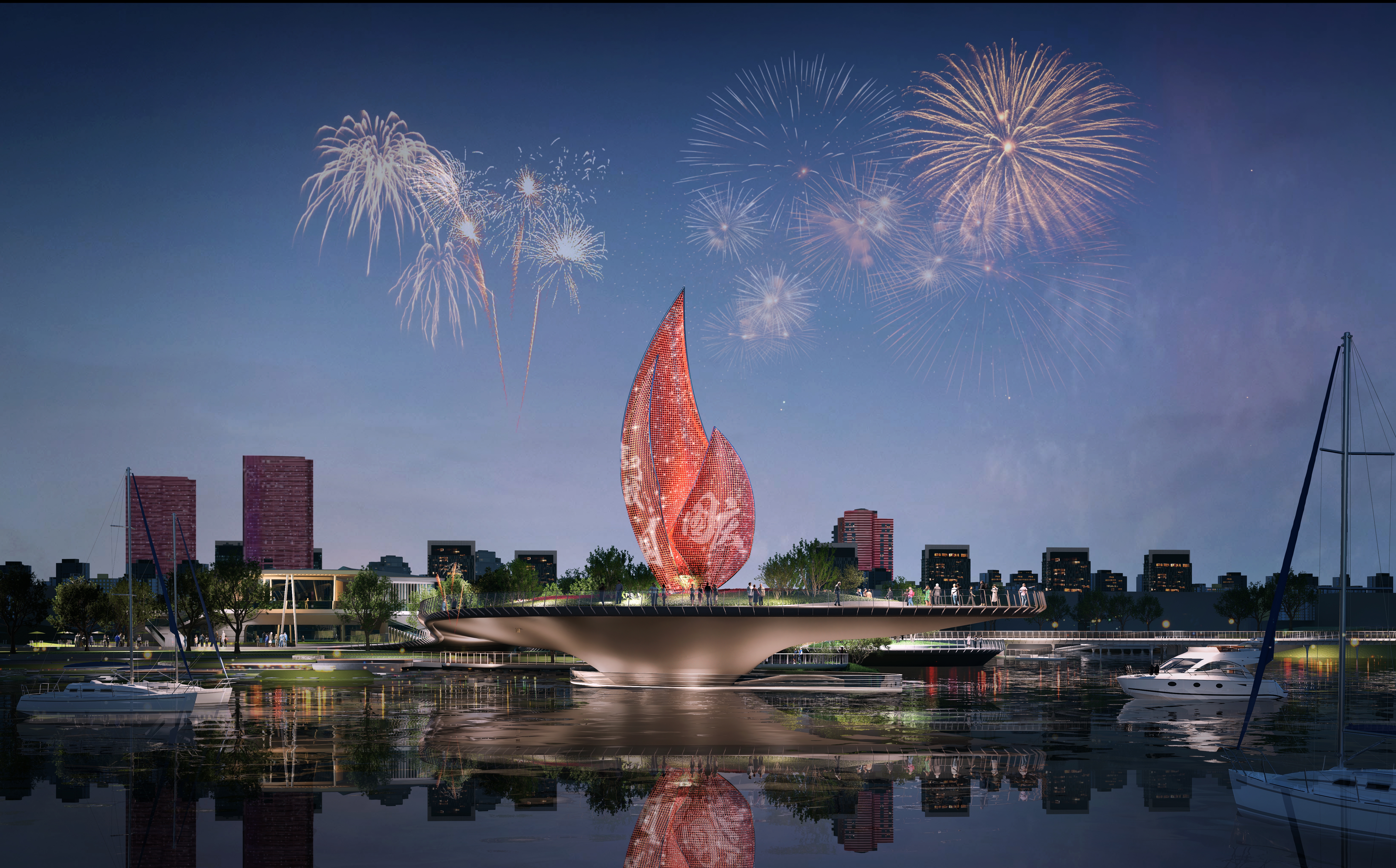
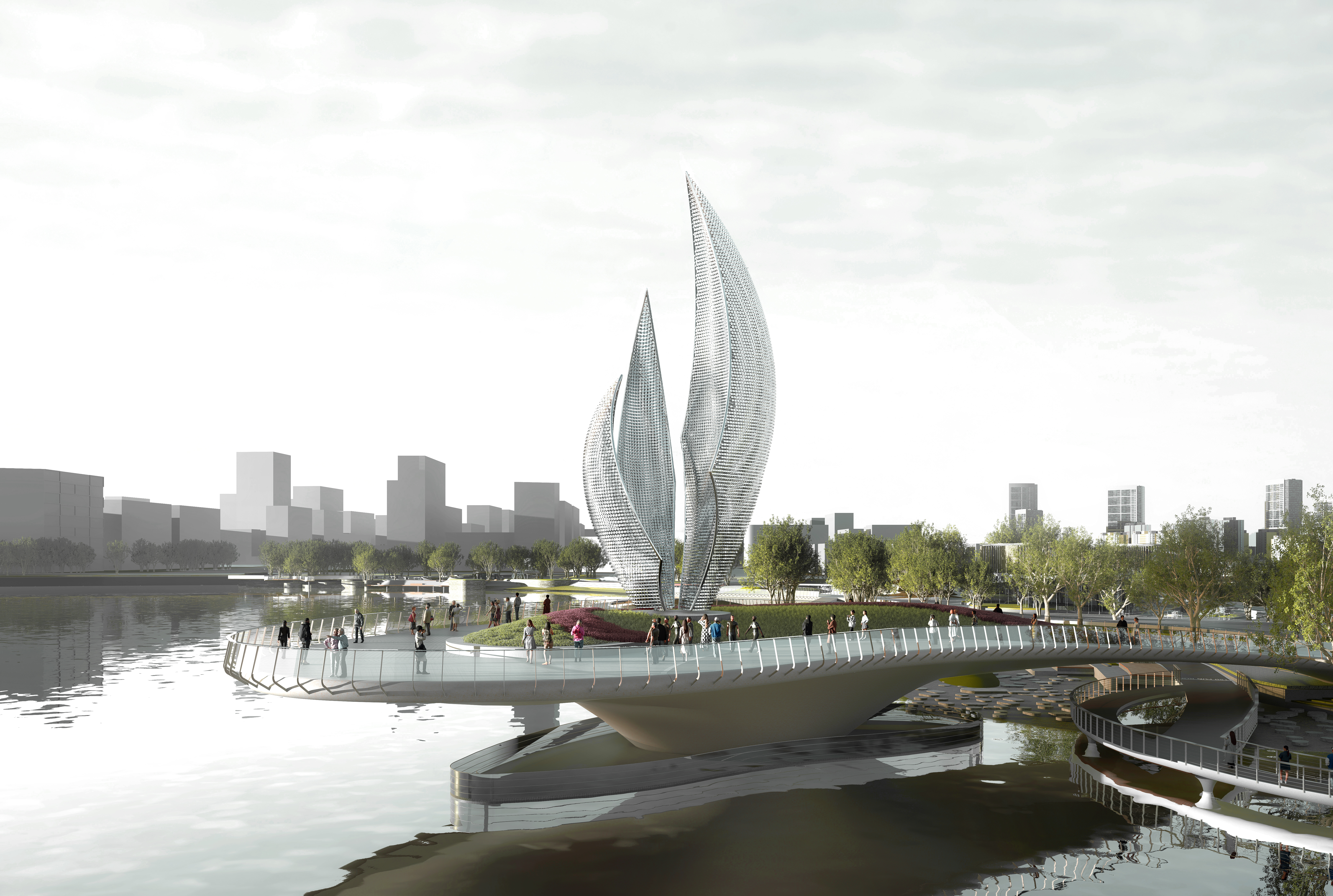
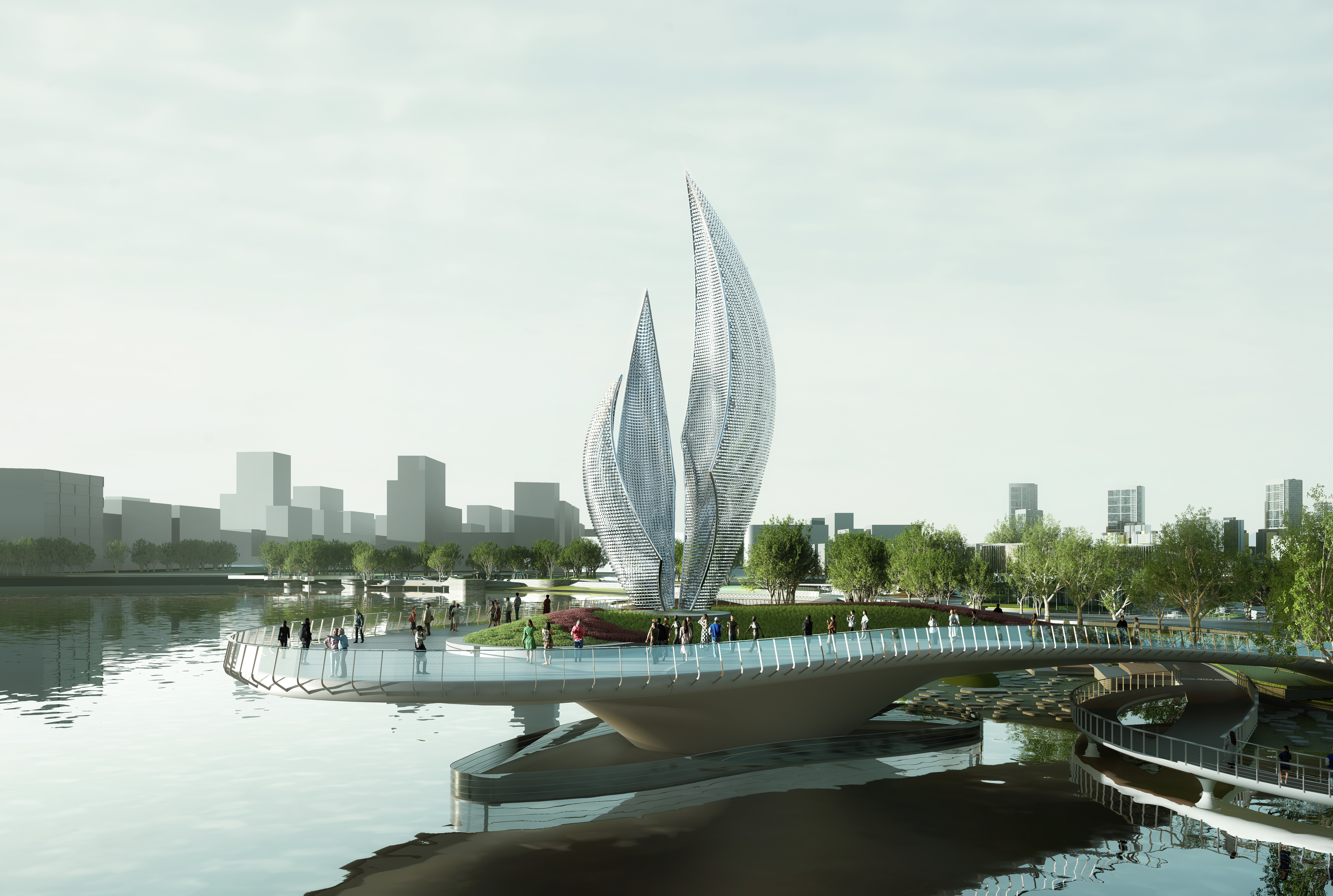
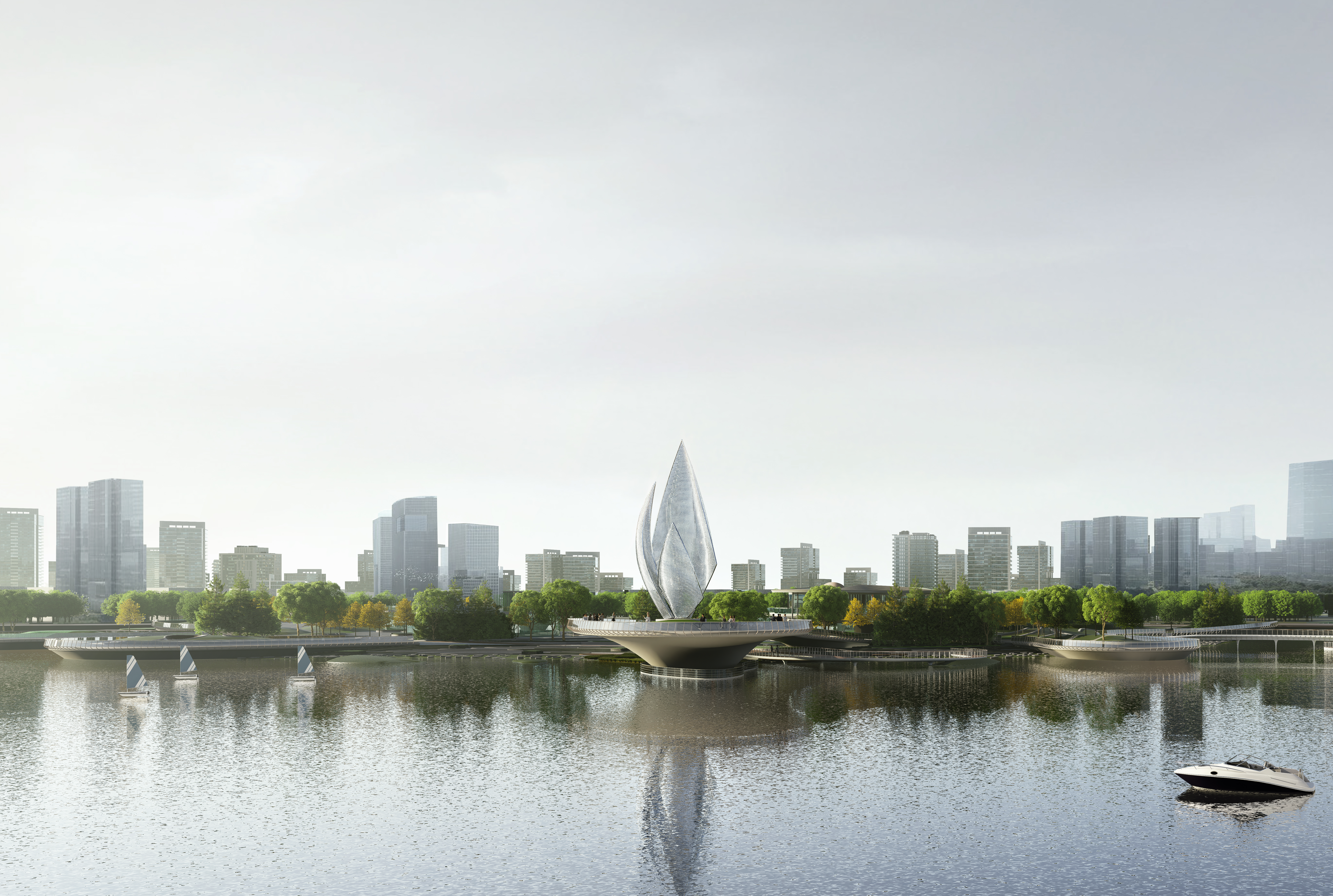
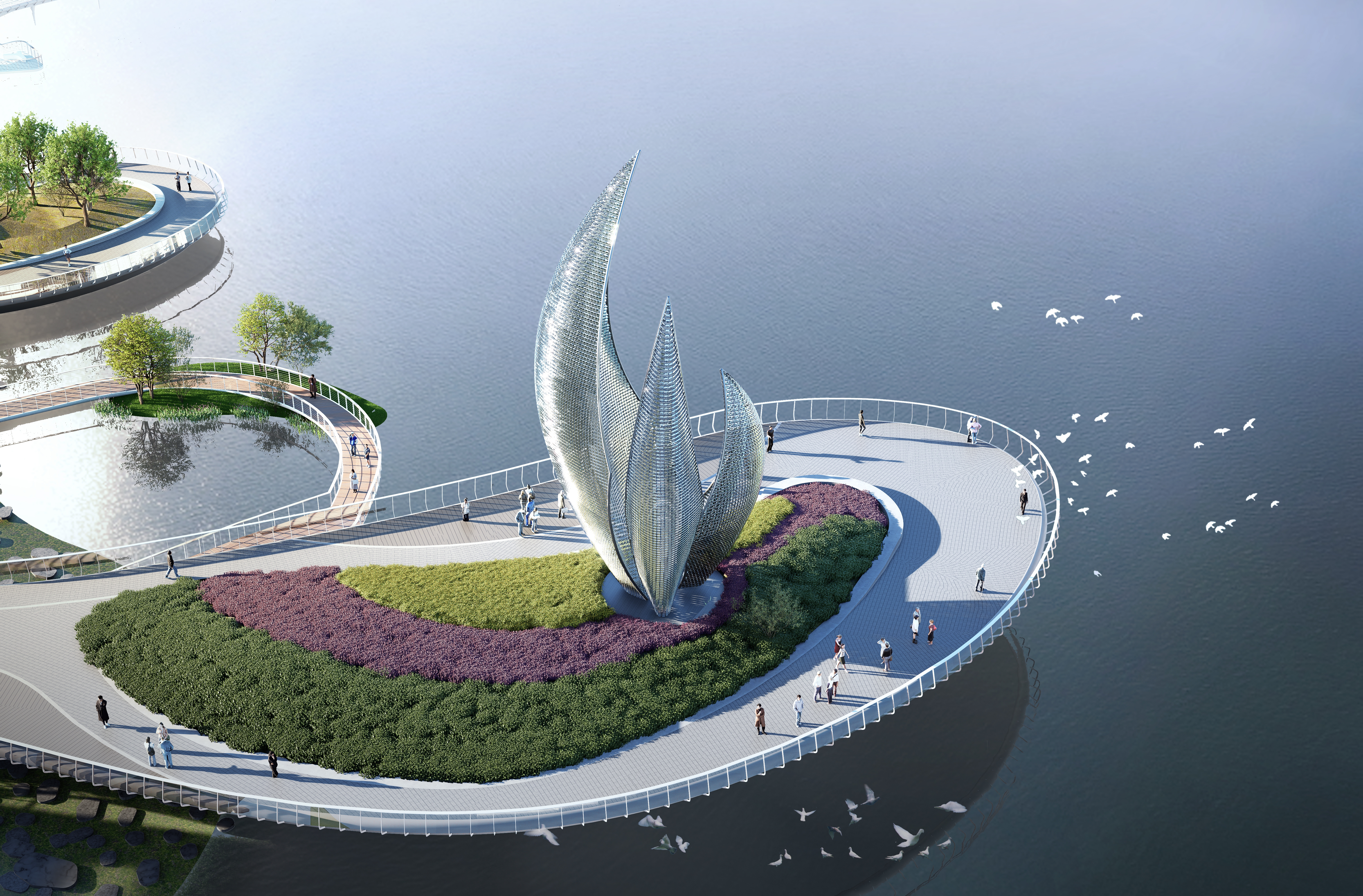
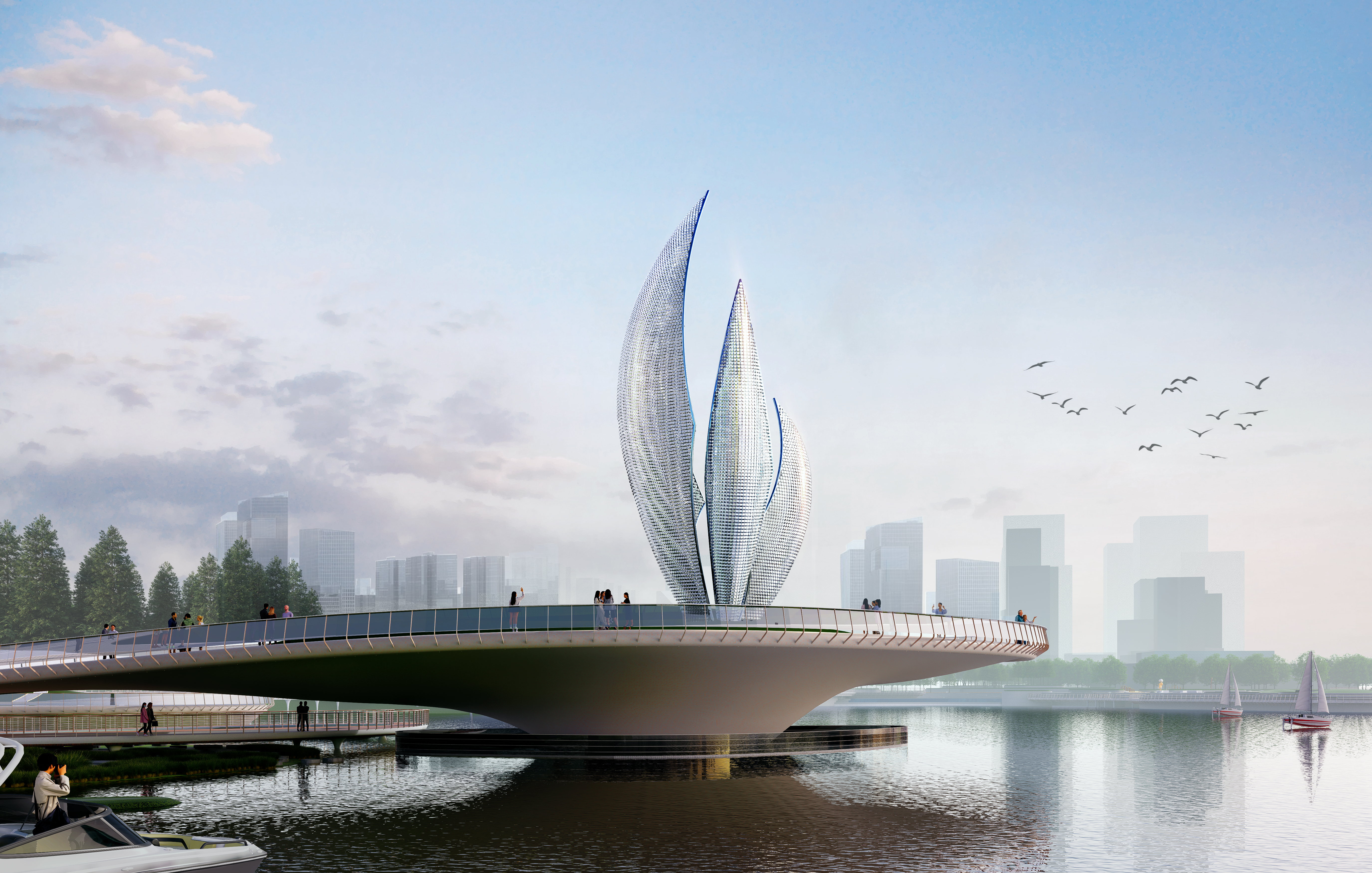
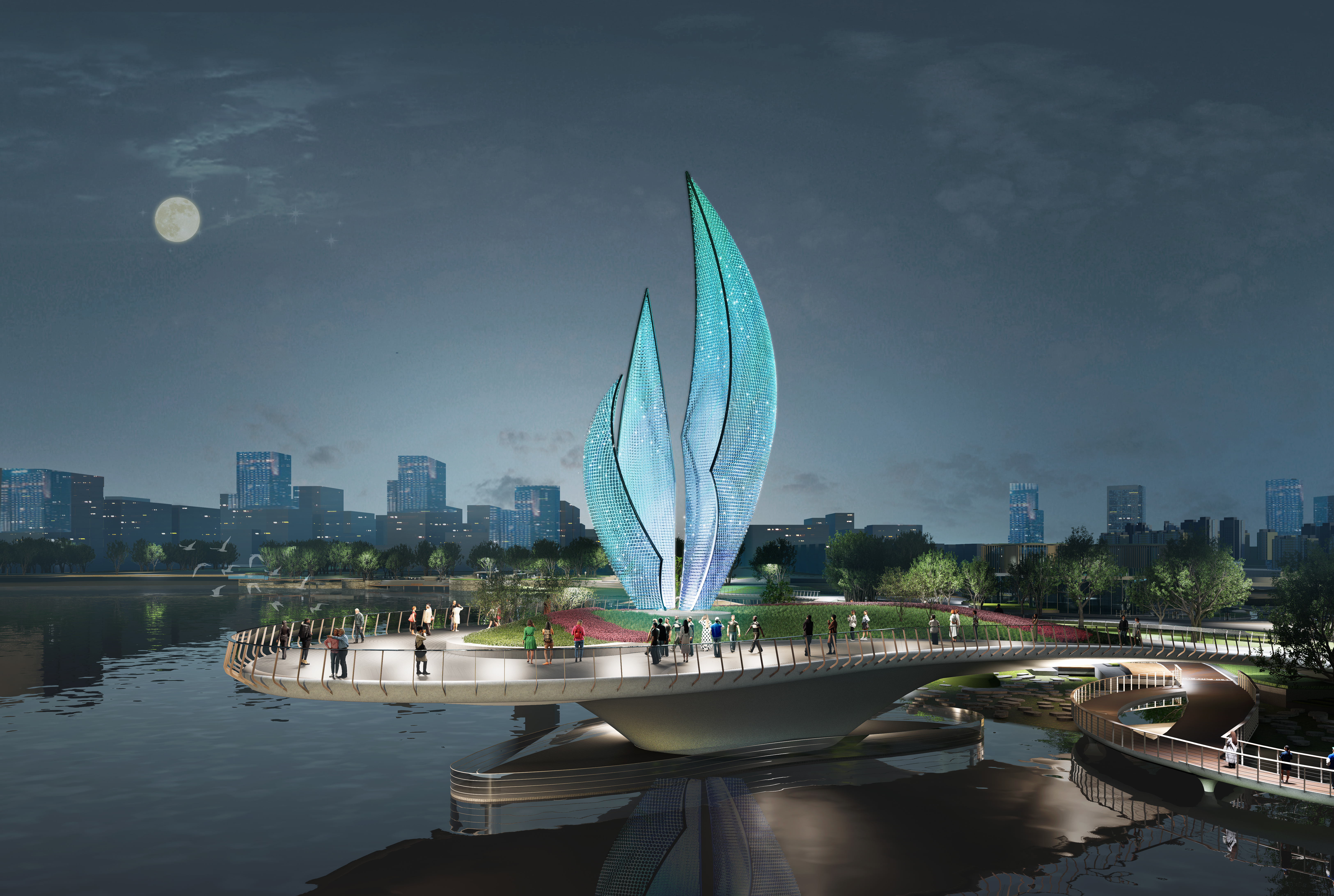
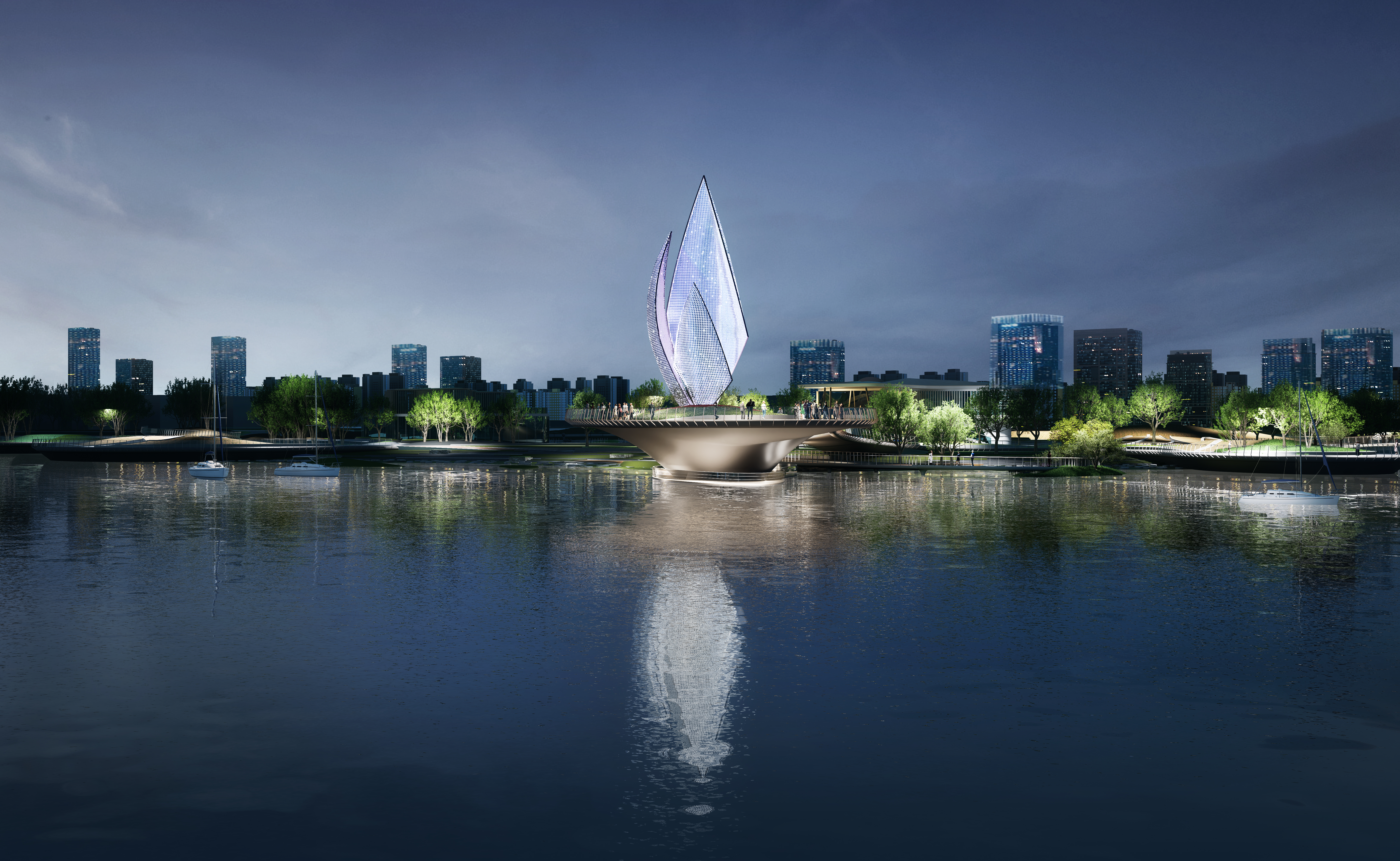
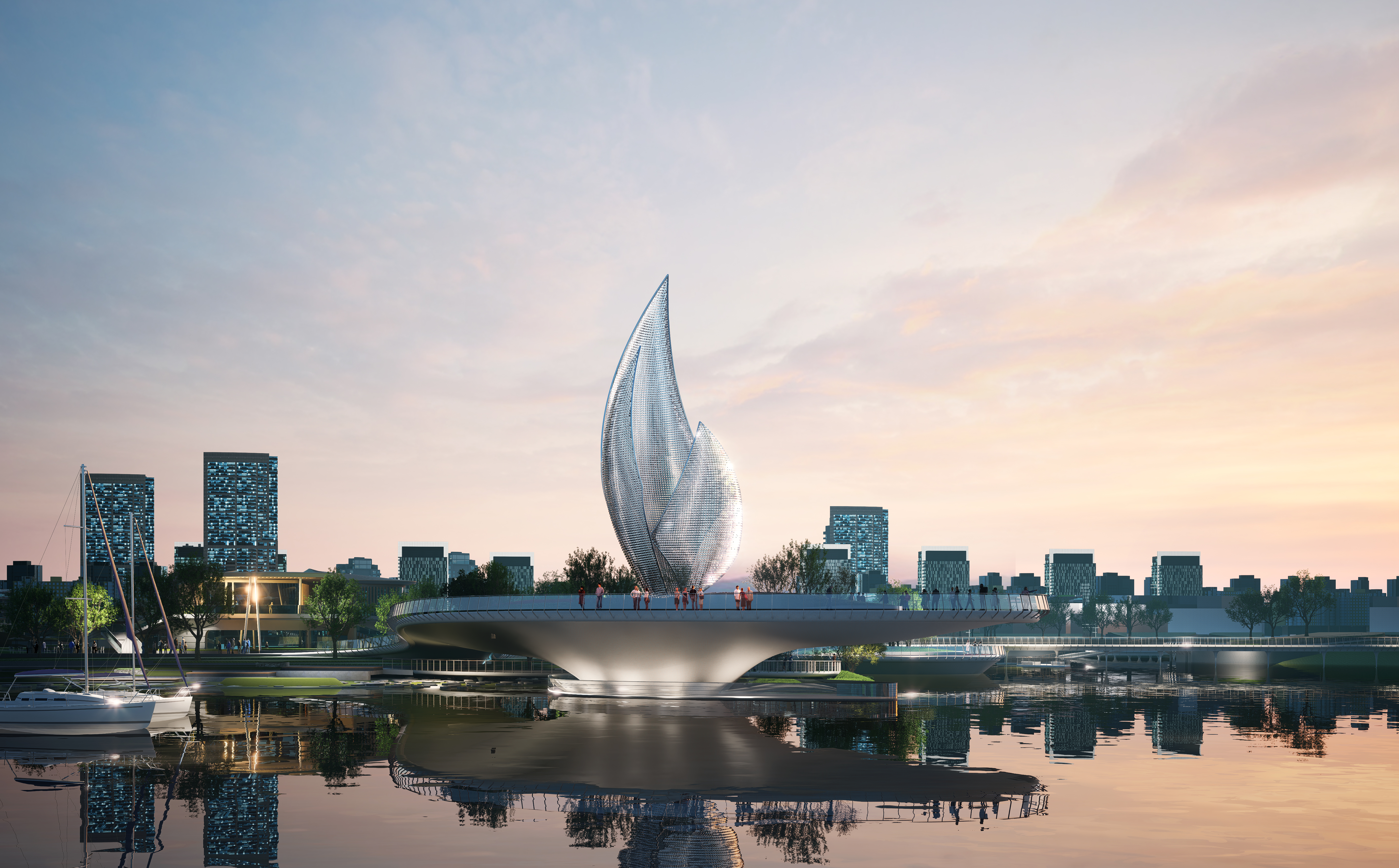
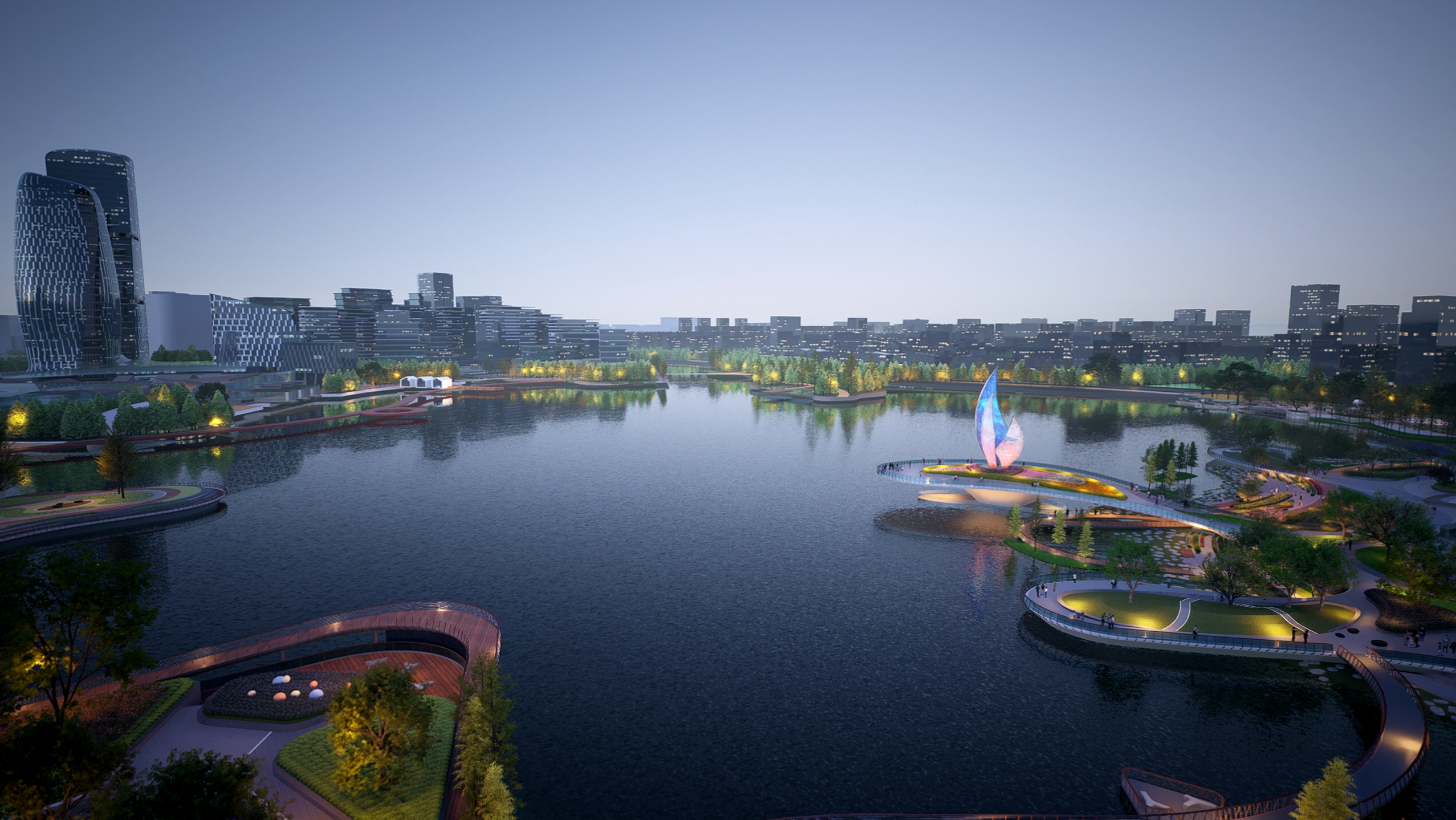
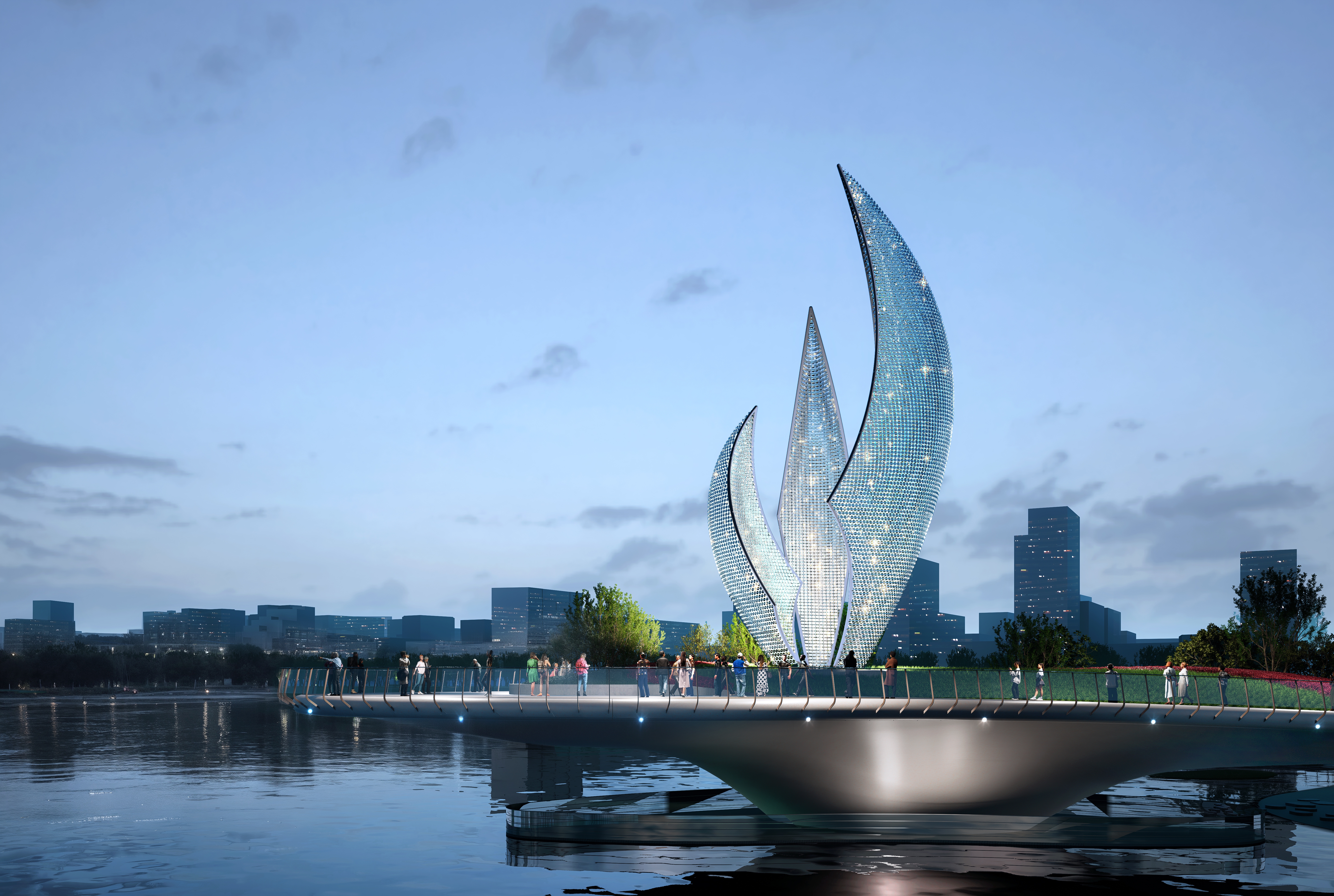
A kinetic landmark at Minghu Lake. Where industrial precision meets fluid artistry, celebrating the journey from raw steel to celestial motion.
A SYNTHESIS OF WIND, LIGHT, AND INDUSTRIAL PRECISION.
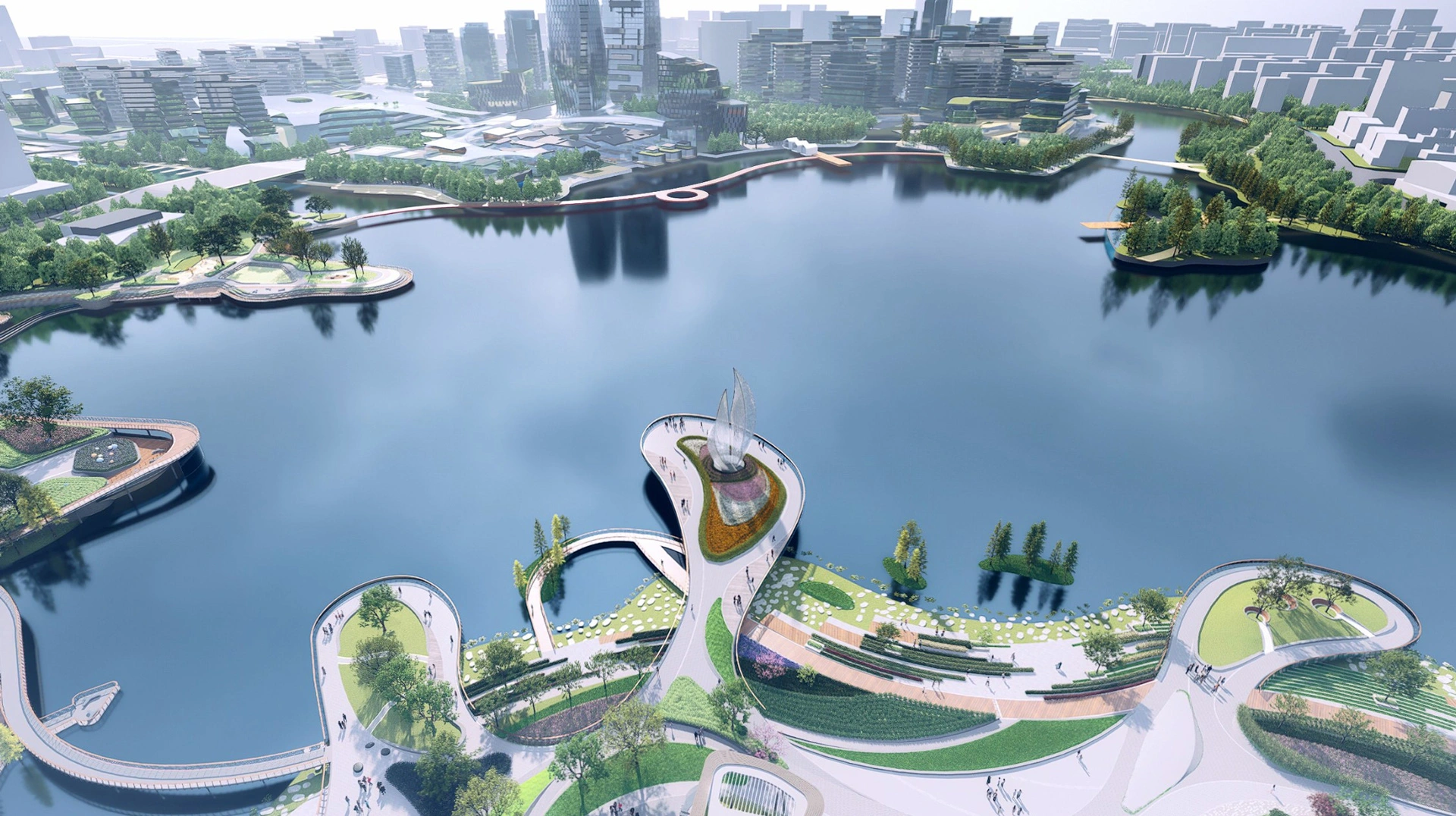
The Minghu Sculpture stands as a monumental kinetic installation designed to interact with the atmospheric conditions of Jinan. It explores the fluid boundaries between heavy metal fabrication and ethereal, natural forces.
| MATERIAL | 316L Stainless Steel |
| FINISH | 8K Mirror Polished |
| DIMENSIONS | 12.4m x 8.2m |
| LOCATION | Jinan, China |

YE FENG
MASTER SCULPTOR
BIOGRAPHY
With over two decades dedicated to monumental public art, Wang Zhe bridges the gap between digital parametricism and physical metalwork, redefining civic spaces globally.
CORE PHILOSOPHY
"DYNAMIC TRANSFORMATION"
A sculpture is not a static object; it is a time-based performance dictated by the environment. It must breathe with the wind and react to shifts in light.
DESIGN & BLUEPRINT
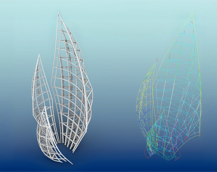
Computational Geometry
Developing the parametric model to ensure structural integrity while maintaining the organic curves of the vision.
Kinetic Simulation
Wind-tunnel digital simulations to optimize the movement of the 48 articulating blades.
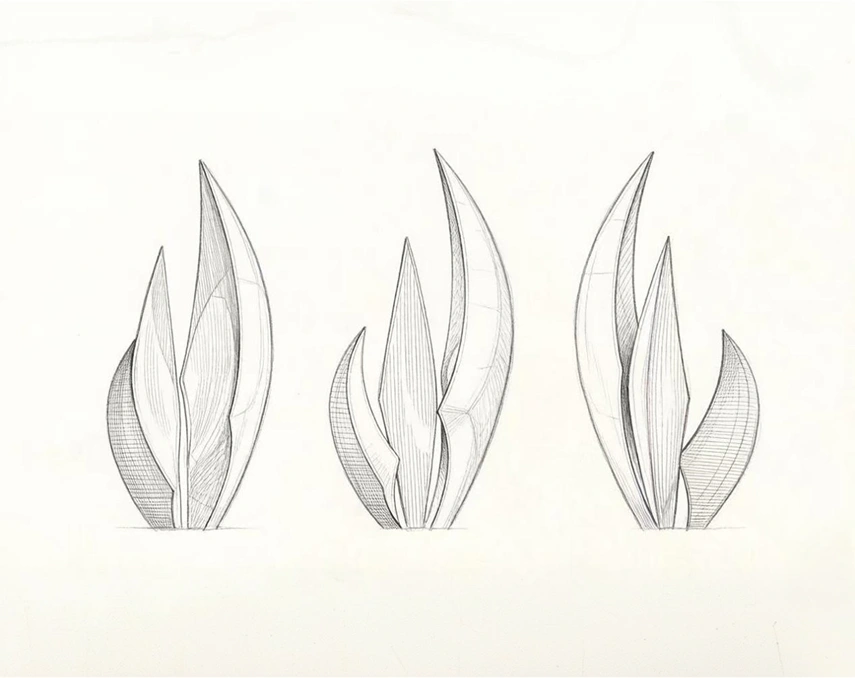
Drafting the Soul
Translating artistic sketches into precise fabrication shop drawings for our artisan team.
MODEL DEDUCTION
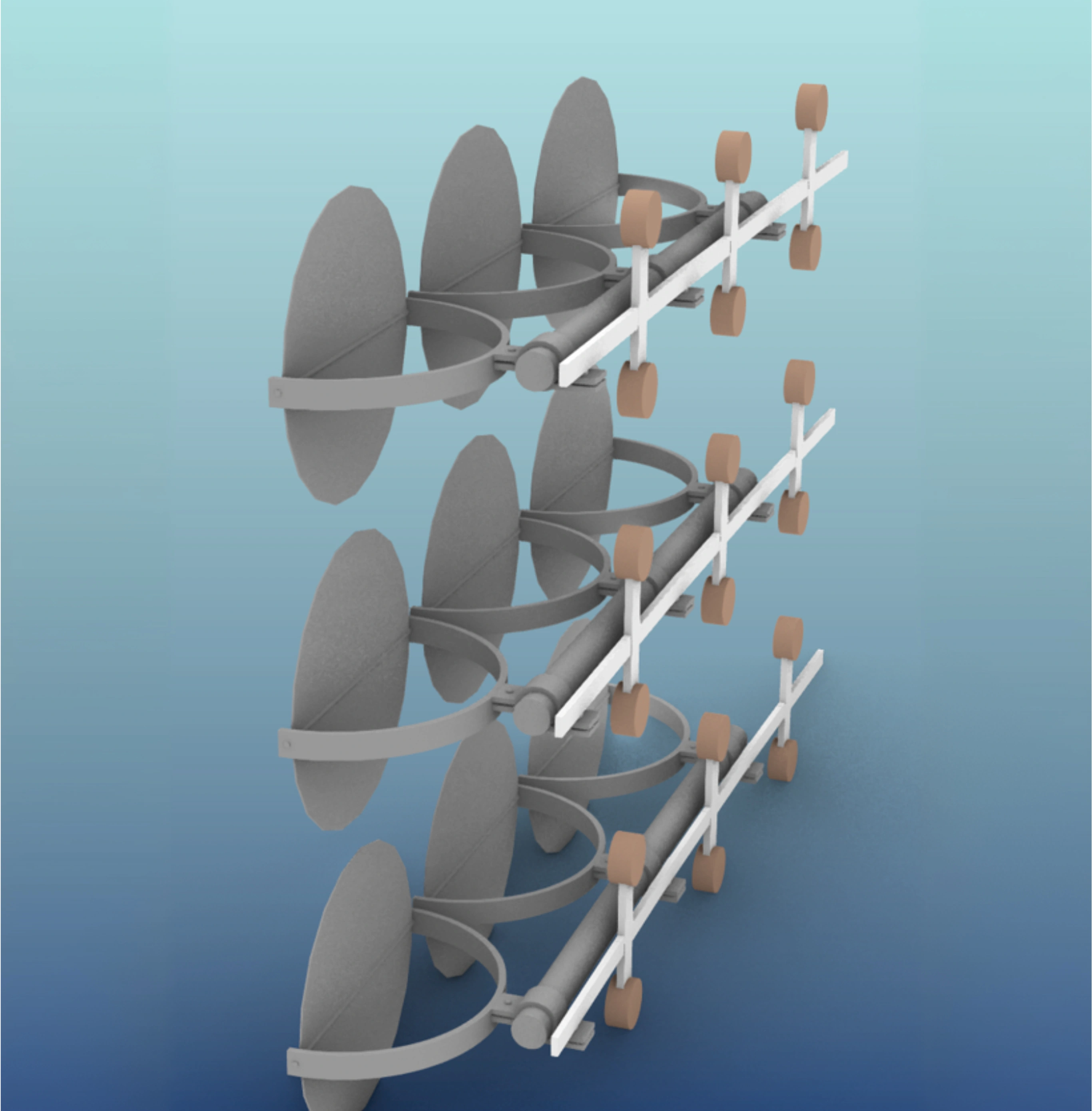
The design deduction and experimental process of the wind-driven blades (iterative deduction, elimination, and final selection of various blade styles).
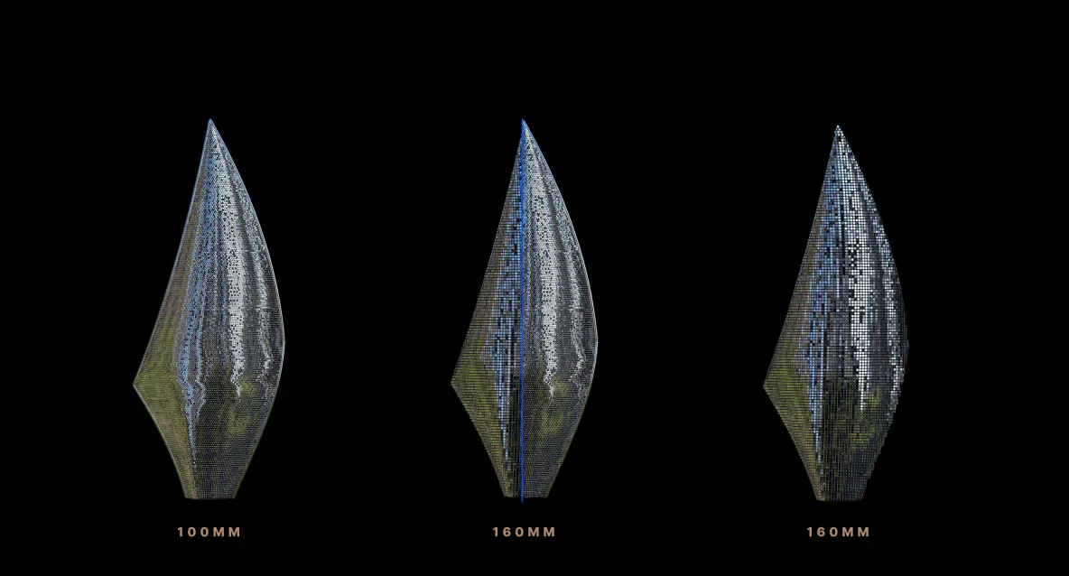
Illumination Tests
Evaluating multiple light sources for optimal brightness and color temperature.
Visual Impact
Assessing how different lighting styles interact with the stainless steel surfaces.
LIGHTING
DEDUCTION
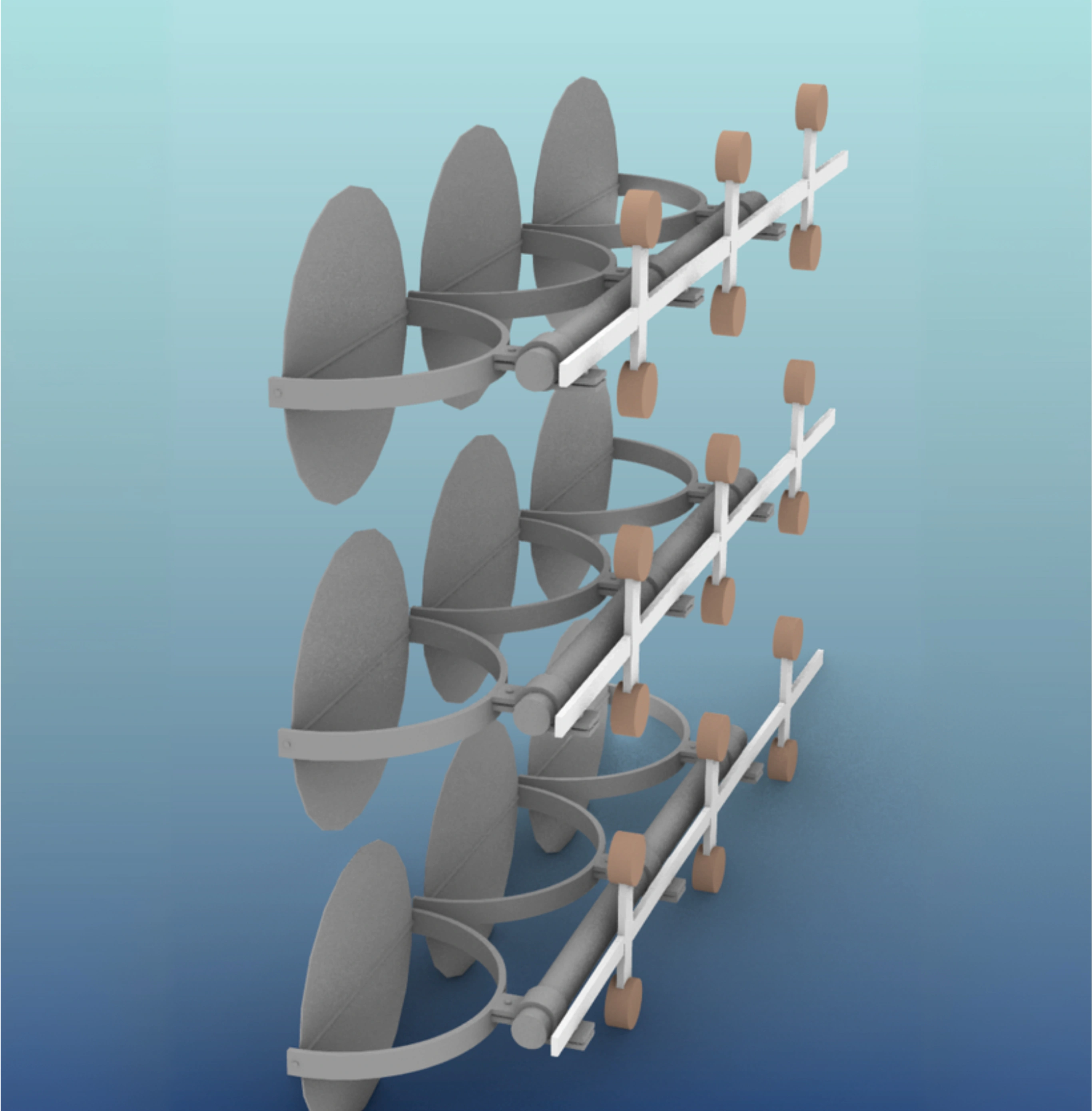
ITERATIVE DEDUCTION
Exploring various lighting styles and configurations to find the optimal interplay.
RIGOROUS ELIMINATION
Systematically testing and discarding lighting options that fail to meet requirements.
FINAL SELECTION
Choosing the ultimate lighting design that perfectly complements the kinetic movement.
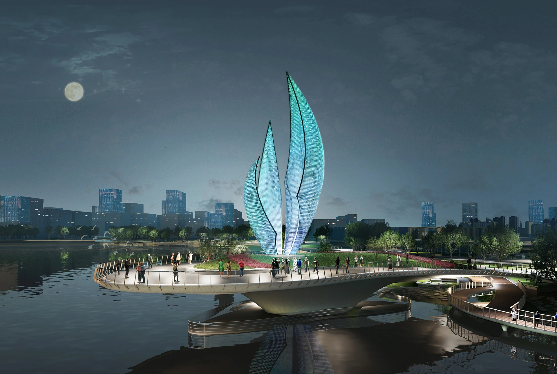
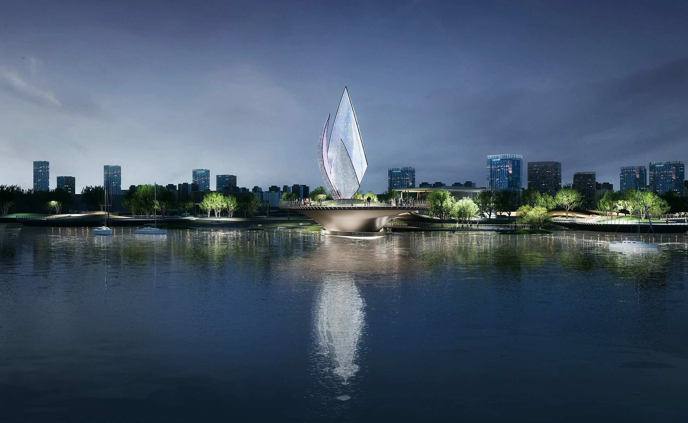
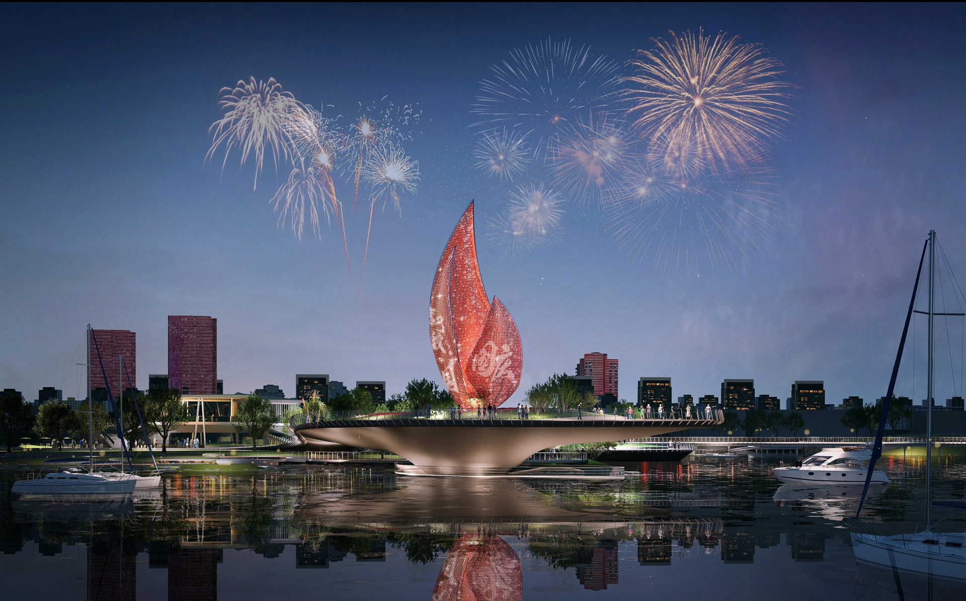
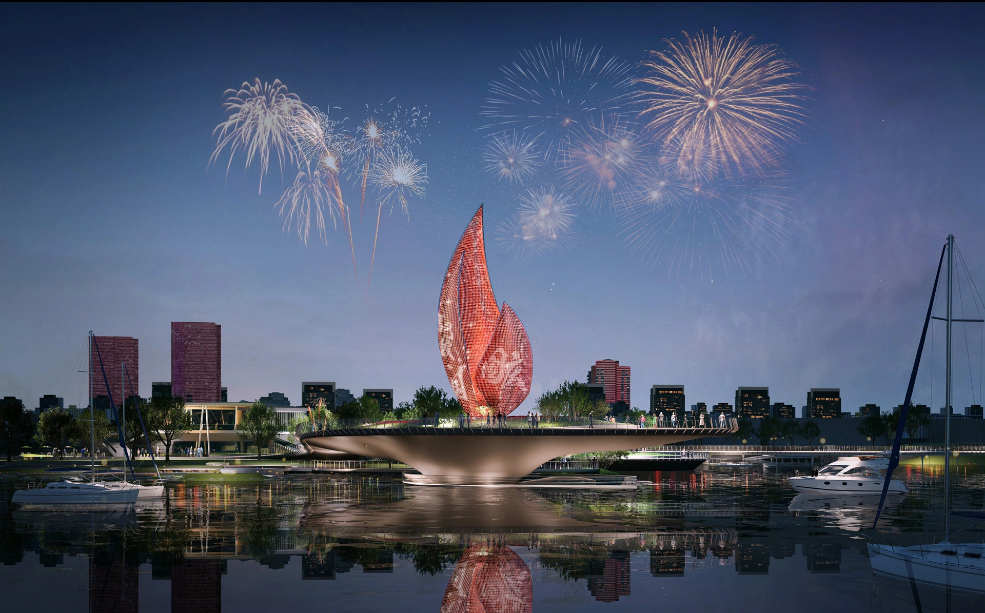
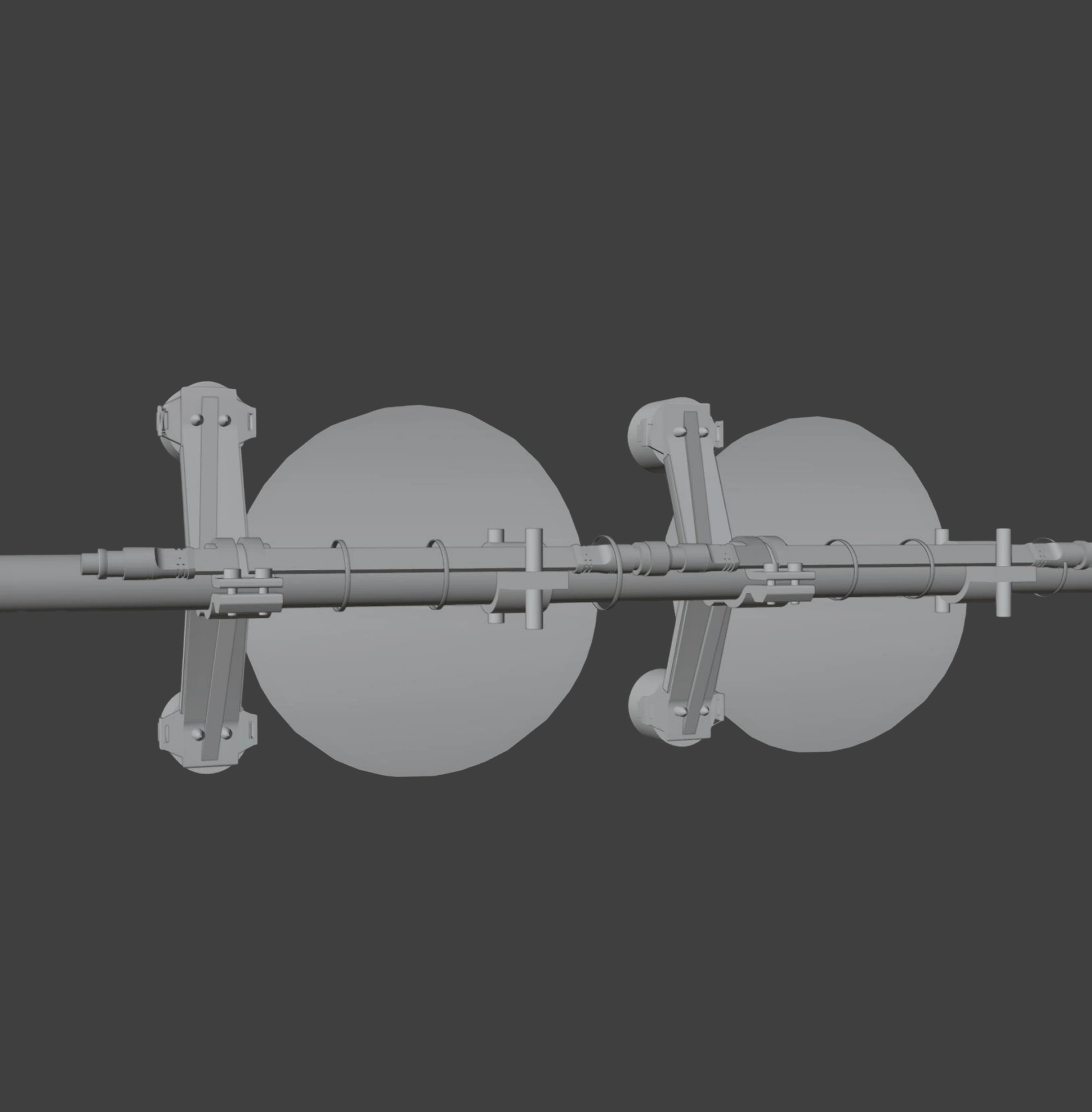
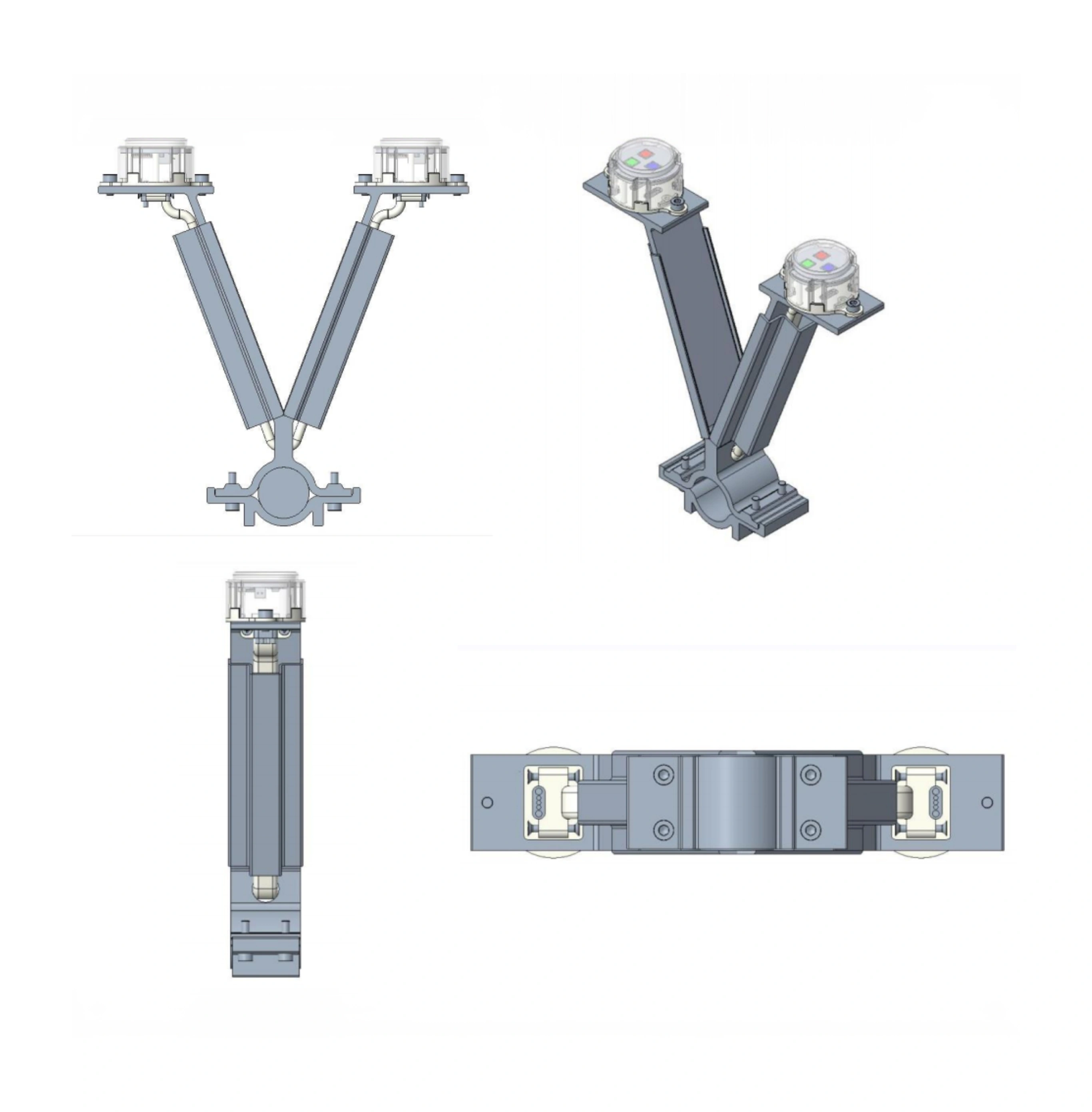
LIGHTING DISPLAY EFFECTS
CRAFTSMANSHIP DEMONSTRATION
Through the analysis of drawings combined with on-site inspection, a specialized and customized lighting installation plan is developed.
TECHNOLOGY SIMULATION
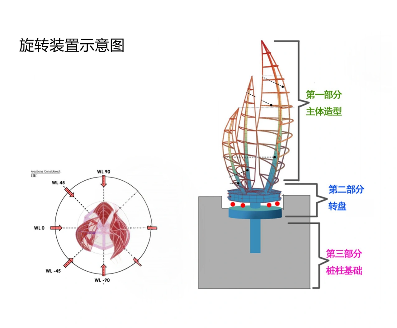
Rotation device diagram
360-degree overall rotation system engineered for seamless kinetic motion. The robust foundation ensures fluid movement under varying wind conditions, minimizing friction and energy loss to provide decades of maintenance-free operation.
360°
Rotation Axis
24/7
Continuous Operation
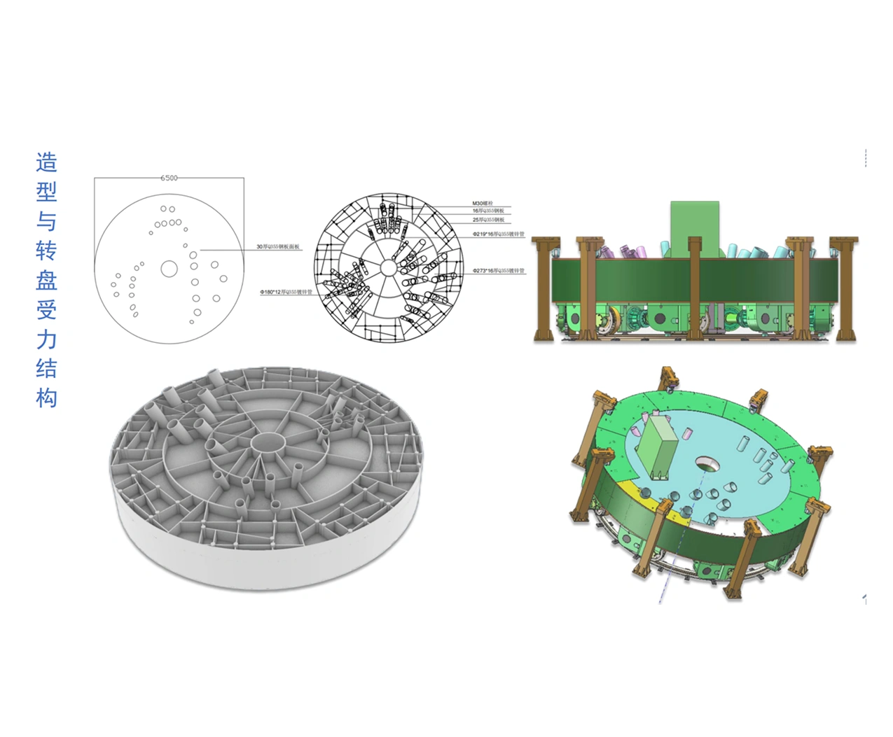
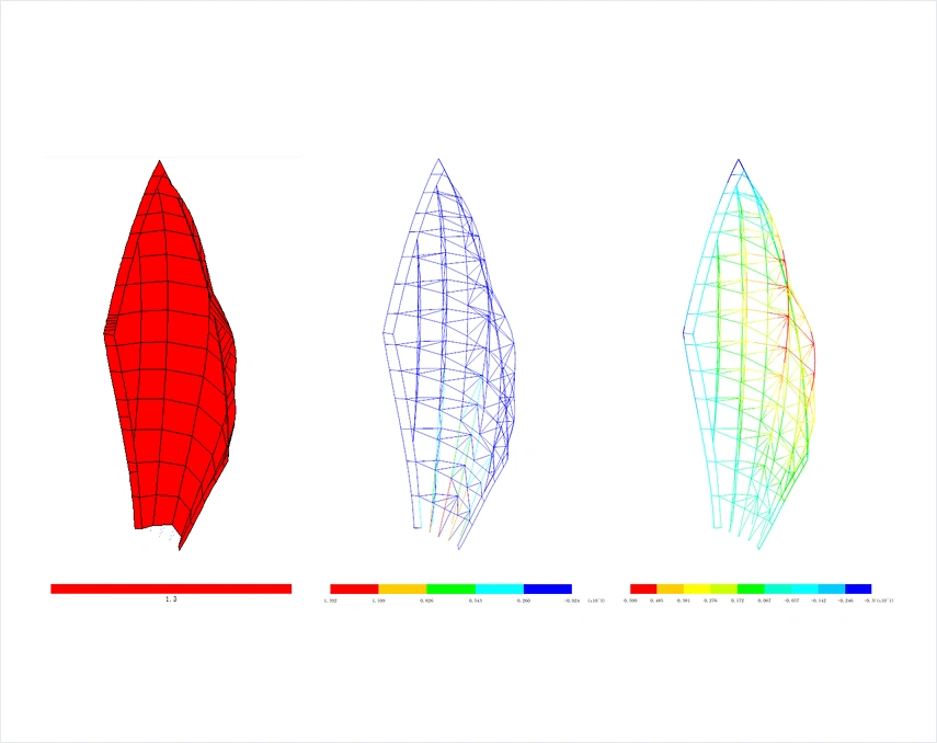
Model construction & force calculation
Graphical and digital display of calculation models and the force calculation process. We simulate structural stress points to optimize material thickness and guarantee structural integrity against maximum local environmental loads.
1.2M
Nodes Computed
100%
Safety Margin
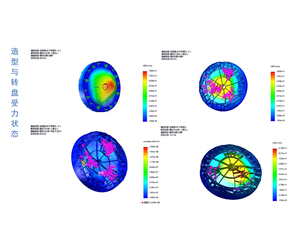
Form & force structure
Analysis of the form and turntable force state, and the internal turntable mechanical structure. Fine-tuning the balance between aesthetic elegance and high-grade mechanical endurance, delivering perfection down to the millimeter.
50+
Wind Scenarios
99.8%
Stability Rating
CONSTRUCTION
& INSTALLATION
Comprehensive documentation of the assembly process, demonstrating the seamless integration of artistic vision and engineering precision in real-world conditions.
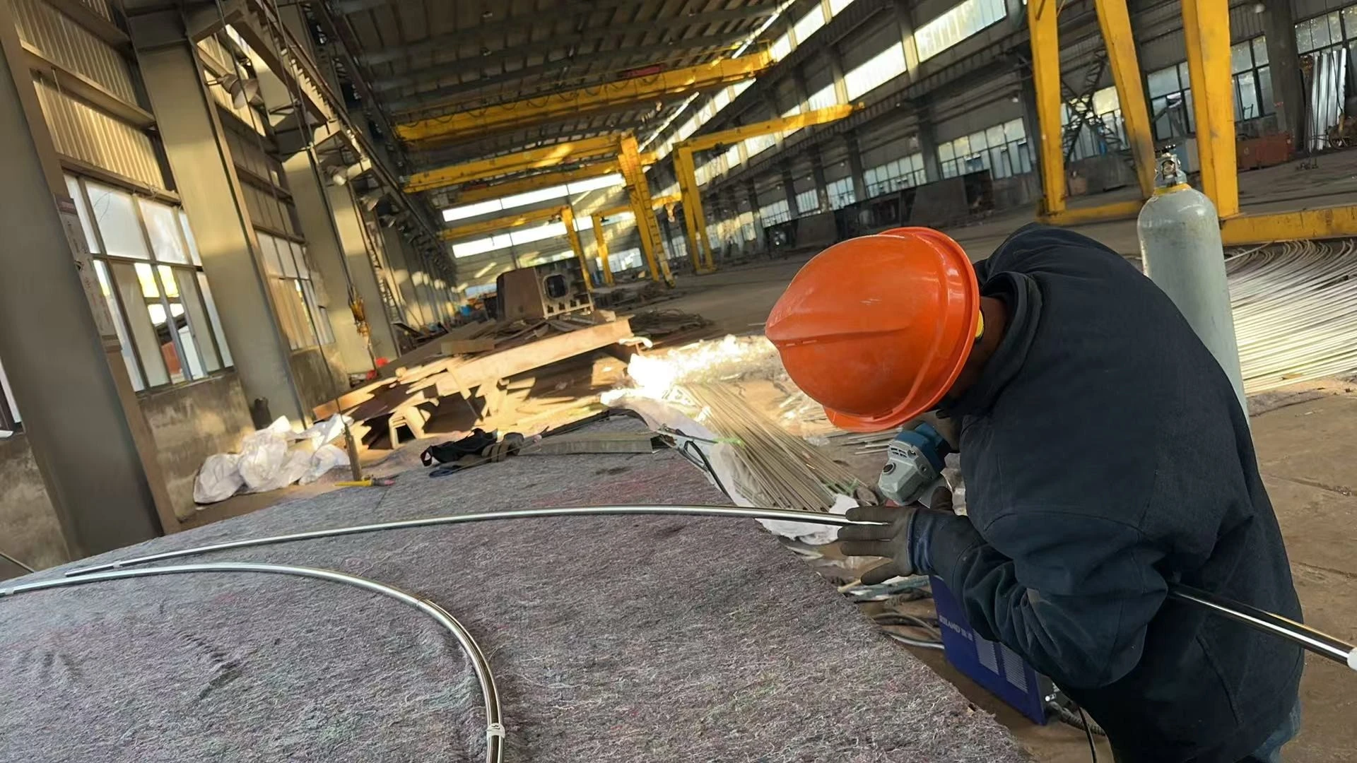
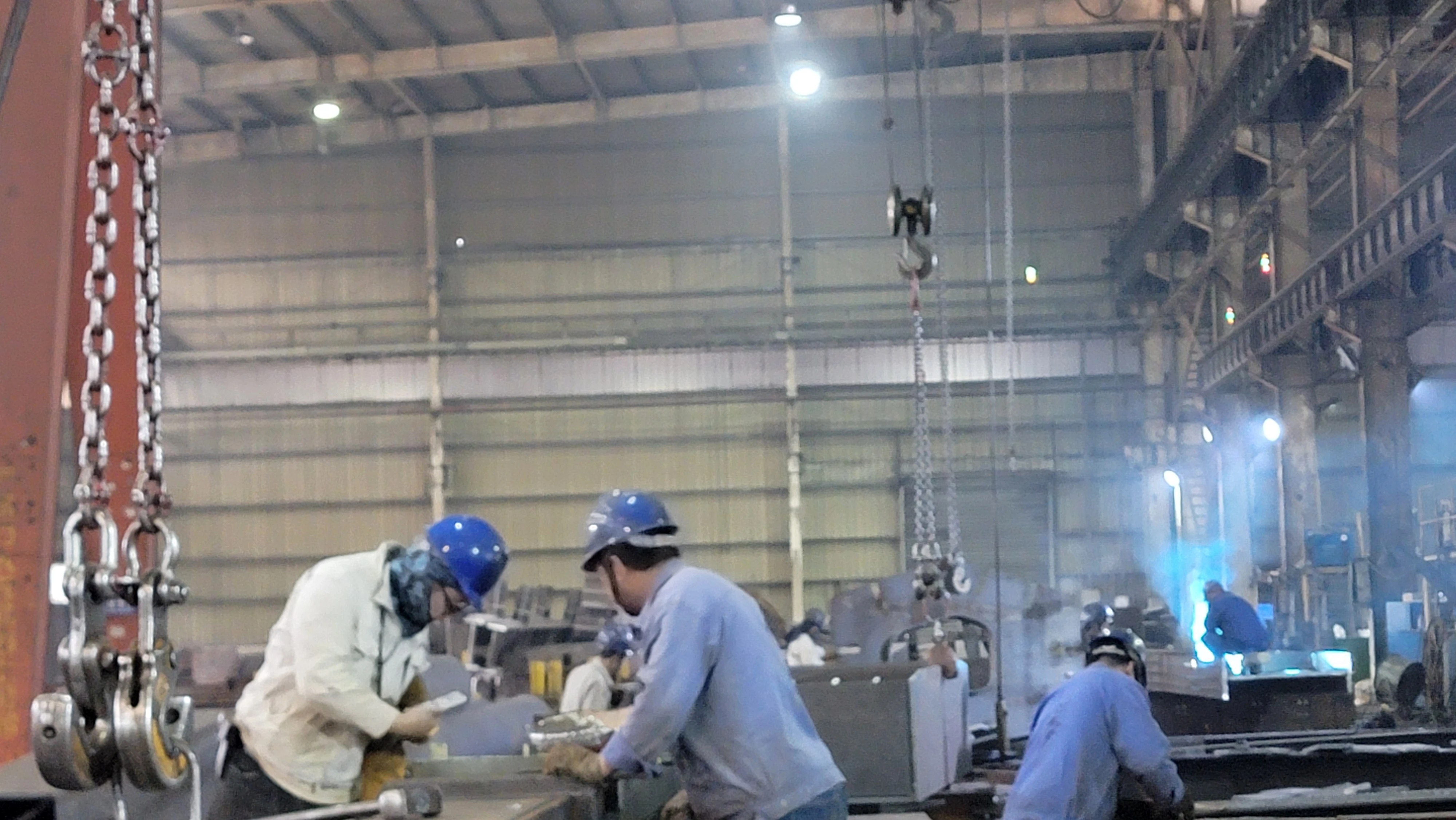
Foundation Laying
Securing the mechanical base deep within the structural footprint to withstand high wind loads and ensure perfect leveling.
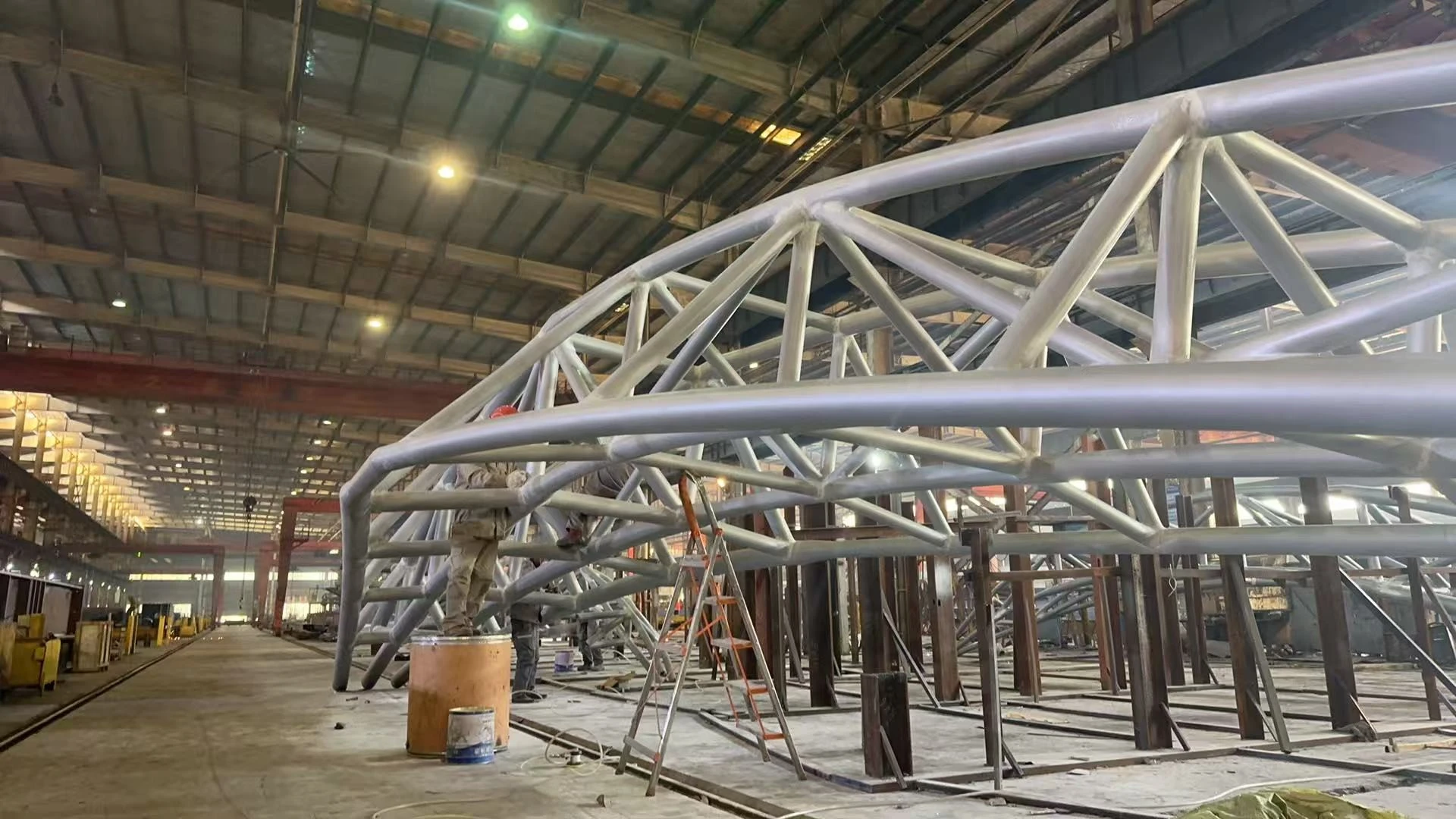
Structural Support
Hoisting the central 316L steel spine using dual crane coordination to guarantee absolute vertical precision under challenging conditions.
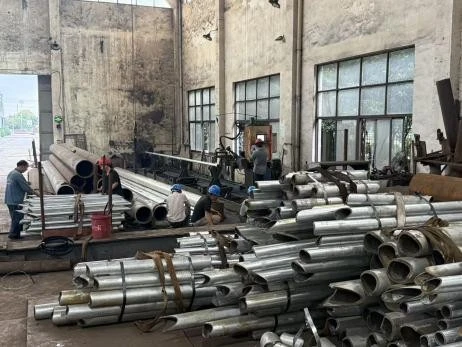
Panel Attachment
Precision mounting of mirror-polished articulating blades and integration of heavy-duty, waterproof electrical systems.


.jpg?imageMogr2/format/webp)

